
Theme. Solving problems on "Constant electric current".
Consider methods for solving problems on the use of Ohm’s law in DC circuits;
Show examples of the application of the Kirchhoff rules for the calculation of complex branched DC circuits.
Course of employment
In the course of conducting the lesson, it is necessary to consider a number of qualitative problems and then solve several calculated problems as their complexity increases.
When solving problems on the laws of direct current, you need to draw an electrical circuit and analyze how the resistors, current sources, and capacitors are connected. If the points of the circuit have the same potentials, they can be interconnected.
Next, calculate the resistance of individual sections of the circuit or the impedance of the circuit and use Ohm's law for sections of the circuit or a closed circuit. If a capacitor is turned on in the DC circuit, no current flows through it. If a resistor is connected parallel to the capacitor, the voltage across the resistor and the capacitor is the same.
The calculation of complex branched chains is carried out using Kirchhoff rules. To do this, arbitrarily choose the direction of the current in all parts of the circuit. They break a complex chain into simple closed circuits, arbitrarily choose the directions of circuit traversal.
Form a system of equations in accordance with the Kirchhoff rules, taking into account the rules for choosing the signs "plus" and "minus".
To solve problems on the conversion of electrical energy into thermal and mechanical use of the law of conservation and transformation of energy.
Qualitative tasks
1. A bare wire bundle consisting of seven and a half turns is stretched between two nails hammered into the plank, to which the ends of the wire are attached. Having connected devices to the nails, they measured the resistance of the chain between the nails. Determine how many times this resistance will change if you unwind the skein, leaving the ends attached to the nails.
2. Five identical resistances are included according to the scheme shown in fig. 1. How will the glow of the right upper helix change if you close the key K?
3. Can currents flow from a lower potential to a higher one?
4. The tram wire broke and lies on the ground. A person in a conductive shoe can only walk up to him in small steps. It’s dangerous to take big steps. Why?

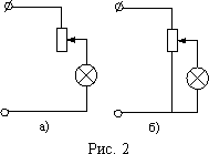
5. In order to turn on the lamp in the network, the voltage of which is greater than the voltage for which the lamp is designed, you can use one of the diagrams shown in fig. 2. Which of these schemes have higher efficiency if in each case the lamp is on in normal mode?

6. In fig. 3 shows two schemes for measuring resistance. Which of them should be preferred when the measured resistance: a) is large; b) a little?
7. Two bulbs with resistance at full heat r and R, and R\u003e r , connect to a source of electromotive force. Both lamps have tungsten filaments. Which of the lamps is lit brighter when connected in series? With parallel connection?
8. The garland of Christmas tree lanterns is made of 40 light bulbs connected in series and powered from the city network. After one light bulb burned out, the remaining 39 light bulbs were again connected in series and connected to the city current network. In which case the room will be brighter: when 40 lights were on or 39?
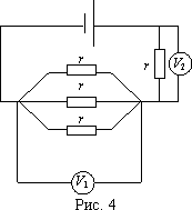
9. What voltmeter reading is greater (fig. 4)? Why?
10. The current passes through the steel wire, which is slightly heated. If one part of the wire is cooled by immersing it in water, the other part is heated up more. Why? (The potential difference at the ends of the wire is kept constant).
11. Two steel wires of the same length, but of different section, are connected in parallel with each other and are included in the electric field network. In which of them will be allocated more heat?
Examples of solving computational problems
Task 1. By copper wire section S = 1 mm 2 current flows by force I = 10 mA. Find the average velocity of the ordered motion of electrons along the conductor, if we assume that for each copper atom there is one conduction electron. Molar mass of copper BUT = 63.6 g / mol, copper density = 8.9 g / cm 3.
Decision:
The current in the conductor is equal to the charge flowing per unit time through the cross section of the conductor
where n - electron concentration q - the charge of one electron, v - the average velocity of an ordered motion, S - the cross-sectional area of the conductor. From (1) we obtain the following expression for the average velocity of the ordered motion of electrons:
Since for each copper atom there is one conduction electron, the concentration of conduction electrons will be equal to the concentration of copper atoms. Consequently, the concentration of conduction electrons will be related to the density of copper by the ratio
where m - mass of one atom.
here N a - Avogadro number. Substituting (4) into (3), we get:
Then the speed of the ordered motion of electrons will look like:
![]()
Answer:
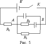
Task 2. In the diagram shown in fig. 5, determine the strength of the current flowing through the battery at the first time moment after the key is closed TO; after a long time. The parameters of the circuit elements and the internal resistance of the source r considered given.
Decision:
At the first moment of time, the capacitors are not charged, and the current in the circuit, according to Ohm’s law, will be equal to
In steady state, current flows through resistances. R 1 and R 3, and the current strength will be equal to
Answer: ![]()
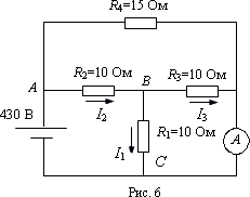
Task 3. What the ammeter will show in the circuit shown in fig. 6?
Decision:
Find the current flowing through the source. We assume that the resistance of the ammeter is very small. Then the electrical circuit can be redrawn as shown in Fig. 7. After that, it is easy to find the resistance of the whole circuit. Resistance R 1 and R 3 are connected in parallel, therefore the resistance of the plot The sun will be equal
![]()
Total resistance of the circuit containing resistance R 1 , R 2 and R 3 will be equal to
Then the total resistance of the entire circuit is determined as follows:
![]()
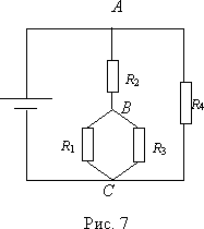
The current flowing through the source, according to Ohm’s law for a complete circuit, will be equal to
where is the electromotive force of the current source.
As can be seen from fig. 6, the current flowing through the source is equal to the sum of the currents flowing through the resistance R 1 and ammeter I A:
Turn again to rice. 7. Since R 123 = R 4, then at the point BUT current I 0 is divided into two equal parts. Through resistor R 2 will go current force I 2 = 2A. At the point AT current I 2 again divided equally between resistors R 1 and R 3 and through a resistor R 1 current goes by force I 1 = 1A.
At the point WITH can write I 0 = I 1 + I A. From here
Answer:
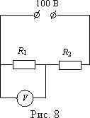
Task 4. The electrical circuit shown in fig. 8. Voltmeter connected in parallel to the resistor with resistance R 1 = 0.4 ohm, shows U 1 = 34.8 V. The voltage at the terminals of the current source is maintained constant and equal to U = 100 V. Find the ratio of the current through the voltmeter to the current through the resistor with resistance R 2 = 0.6 ohm.
Decision:
The voltage across the resistor R 2 will be equal to U - U 1, and the current flowing through this resistor, according to Ohm’s law for a homogeneous section of the circuit,
![]()
where I 1 is the current flowing through the resistor with resistance R 1, and I V is the current through the voltmeter. From here
Answer: ![]()
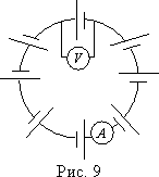
Task 5. Several current sources are connected as shown in fig. 9. What are the indications of the ideal ammeter and voltmeter included in the circuit? The resistance of the connecting wires is neglected.
Decision:
Case 1. We believe that all sources are the same, that is, they have the same electromotive force and internal resistance r. Let the number of sources be n. Then, using Ohm's law for a closed circuit, we get:
This will be the ammeter reading. From Ohm’s law for a non-uniform part of the circuit, it follows that the voltmeter reading will be
Case 2. All sources are different. Then the ammeter will show the current
Obviously, the voltmeter reading in this case
Answer: if all current sources are the same, then ![]() if the electromotive forces of the current sources are different, then
if the electromotive forces of the current sources are different, then 
Task 6. Find the capacitor voltage across capacitors. WITH 1 and WITH 2 in the circuit shown in fig. 10, if it is known that during a short circuit, the current passing through the source increases in n time. WITH 1 , WITH 2 are known.
Decision:
The voltage across a resistor connected in parallel to the capacitors,
where U 1 and U 2 - voltage on the first and second capacitors, respectively. Capacitors are connected in series, therefore, the charges on them will be the same.
Solving together the equation (5) and (6), we get:
![]() (7)
(7)
No current flows through capacitors, therefore Ohm’s law for the circuit in question is written as:
where r - internal resistance of the source, I - the current flowing through the source and resistor. The voltage drop across the resistor, according to Ohm’s law for a homogeneous section of the circuit,
Short-circuit current corresponds to R = 0, i.e.
According to the condition of the problem
Substituting the value I and I 0 in the last relation, we get:
From here R = r(n -one). Substituting the value R in (8), we get
After substituting I in (9) we get:
Substituting the found value U in (7), we get:
Answer:
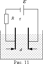
Task 7. A liquid dielectric is placed between the plates of a flat capacitor (Fig. 11). The liquid level rises every second evenly. h. The plates are connected in series with a constant current source, whose electromotive force, and resistance R. Determine the current in the circuit. Plate width lthe distance between them ddielectric constant of dielectric.
Decision:
At each moment in time, a capacitor partially filled with a liquid can be considered as a combination of two capacitors, air and filled with liquid, connected in parallel. The capacitance of parallel-connected capacitors is equal to the sum of their capacitors. For every second part of the plate height h released from dielectric. This leads to a change in capacitance on
![]() (10)
(10)
The charge then flows from the plates of the capacitor and a current flows in the circuit, the force of which
Since the voltage between the capacitor plates does not change, the charge change on the capacitor plates per unit time will be equal to
![]() (12)
(12)
Then after substitution in (12) we get:
![]()
that is, the current in the circuit will be equal
![]() (13)
(13)
The voltage on the capacitor plates can be found from Ohm’s law for a complete circuit.
Substituting the value U in (13), we obtain for the current strength the following expression:
![]()
Answer: ![]()
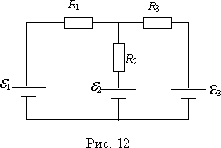
Task 8. In the diagram in fig. 12 1 = 2 V, 2 = 4 V, 3 = 6 V, R 1 = 4 ohms, R 2 = 6 ohms, R 3 = 8 ohms. Find the strength of the current in all areas.
Decision:
We use the rules of Kirchhoff. Set the direction of currents I 1 , I 2 , I 3 As independent circuits, choose a large loop containing current sources 1 and 3, and a small loop containing current sources 1 and 2. We will go around the contours clockwise (Fig. 13). Then you can make the following system of equations:
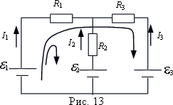

Solving the system of equations for currents, we obtain the following values:
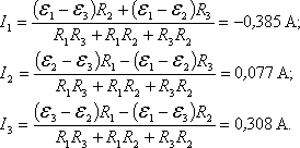
Minus sign means current I 1 flows in the opposite direction to the selected one.
Answer: 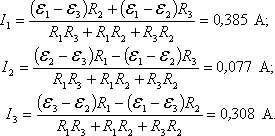
Task 9. Battery electromotive force = 16 V, internal resistance r = 3 ohms. Find the resistance of the external part of the circuit, if it is known that it releases power R = 16W. Determine the efficiency batteries.
Decision:
If the external resistance is R, it allocates useful power P = I 2 R. The strength of the current in the circuit can be found from Ohm’s law for the complete circuit:
The last expression can be rewritten as a quadratic equation with an unknown R:
![]()
The solution to this equation is:
![]()
Substituting in the resulting solution numbers, we get R 1 = 1 ohm; R 2 = 9 ohms. These two resistance values correspond to the efficiency:
Answer:

Task 10. Through two series-connected conductors with the same cross sections Sbut different specific resistances 1 and 2 (2\u003e 1), the current flows by force I (Fig. 14). Determine the sign and magnitude of the surface charge density that occurs at the interface of the conductors.
Decision:
We use the Gauss theorem for electric fields. As an arbitrary closed surface through which we calculate the flux of the electric field intensity vector, we choose a cylindrical surface whose lateral surface coincides with the surface of the conductor (Fig. 15). The electric field strength vectors in the conductor are parallel to the side surface of the cylinder; therefore, only flows through the bases of the cylindrical surface contribute to the intensity vector flow. Since each conductor is electrically neutral, only charge is uncompensated inside this surface. q at the interface of the conductors. Therefore, the Gauss theorem is written as follows: 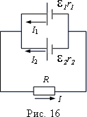
2. A battery consisting of two identical elements connected in parallel with electromotive forces = 2 V is closed by a resistor whose resistance R = 1.4 ohm (Fig. 16). Internal resistance of elements r 1 = 1 ohm and r 2 = 1.5 ohms. Find the currents I 1 , I 2 , Iflowing in the circuit.
Answer: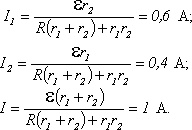
3. Two consumers whose resistances are R 1 and R 2, are connected to the DC network for the first time in parallel, and the second - in series. In which case the power consumed from the network will be more?
Answer:![]()
4. The resistor and the capacitor are connected in series with a source of electromotive force, while the charge on the capacitor plates q 1 = 610 -4 Cl. If the resistor and the capacitor are connected to the source of electromotive force in parallel, then the charge on the capacitor plates q. How much heat is released on the resistor with resistance R after key closure TO? The internal resistance of the source is neglected.
Answer:
8. Find the total electron momentum in the wire length l = 1000 m through which current flows by force I = 70 A.
Answer:
9. How many times the additional resistance (shunt) should be greater than the resistance of the voltmeter, so that this voltmeter allows you to measure the voltage in n = 10 times more than what it is designed for?
Answer: at (n - 1) time.
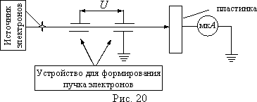
10. Electron beam passes accelerating potential difference U = 1000 V and, falling on a metal plate, is completely absorbed. In this case, the microammeter connected between the plate and the "ground" shows the current I = 10 -3 A (fig. 20). Determine the temperature of the metal plate after it absorbs the electron beam, if the initial temperature of the plate was T 0 = 300 K. The heat capacity of the metal plate WITH = 10 J / K, beam duration t = 100 c. To assume that all the heat released in the plate goes to heat it.
Answer: ![]()
1. Boutiques E.I., Kondratiev A.S. Physics. T. 2. Electrodynamics. - M .: Fizmatlit: Laboratory of basic knowledge; SPb .: Nevsky dialect, 2001. - p. 11-82.
2. Belolipetsky S.N., Erkovich OS, Kazakovtseva V.A. and others. Questbook on physics. - M .: Fizmatlit, 2005. - p. 123-142.
3. Gotovtsev V.V. The best tasks in electricity. - M .; Rostov n / D: Publishing Center "Mart", 2004. - p. 59-116.
\u003e\u003e Physics: Electronic Conductivity of Metals
Let's start with metallic conductors. The current-voltage characteristic of these conductors is known to us, but so far nothing has been said about its explanation from the point of view of the molecular kinetic theory.
Carriers of free charges in metals are electrons. Their concentration is high - about 10 28 1 / m 3. These electrons are involved in indiscriminate thermal motion. Under the action of an electric field, they begin to move in an orderly manner with an average speed of the order of 10 -4 m / s.
Experimental evidence of the existence of free electrons in metals. Experimental evidence that the conductivity of metals is due to the movement of free electrons was given in the experiments of LI Mandelstam and ND Papaleksi (1913), B. Stewart and R. Tolman (1916). The scheme of these experiments is as follows.
The coil is wound on a wire, the ends of which are soldered to two metal discs, isolated from each other ( rice.16.1). A galvanometer is connected to the ends of the disks with the help of sliding contacts.
The coil is brought into rapid rotation, and then abruptly stopped. After the coil stops abruptly, the free charged particles move for some time relative to the conductor by inertia and, therefore, an electric current arises in the coil. The current exists for an insignificant time, because of the resistance of the conductor, the charged particles decelerate and the orderly movement of the particles forming the current stops.
The direction of current in this experience suggests that it is created by the movement of negatively charged particles. The charge transferred in this case is proportional to the ratio of the charge of the particles creating the current to their mass, i.e. | q | / m. Therefore, by measuring the charge passing through the galvanometer during the existence of a current in the circuit, it was possible to determine this ratio. It turned out to be 1.8 10 11 C / kg. This value coincided with the ratio of the electron charge to its mass e / mpreviously found from other experiences.
The movement of electrons in the metal. Electrons under the influence of the force acting on them from the electric field, acquire a certain speed of ordered motion. This speed does not increase further with time, since, by colliding with the ions of the crystal lattice, the electrons lose their directional motion, and then again under the action of an electric field they begin to move directionally. As a result, the average velocity of the ordered motion of electrons is proportional to the electric field strength in the conductor. v ~ E and, therefore, the potential difference at the ends of the conductor, since  where l - conductor length.
The strength of the current in the conductor is proportional to the speed of the ordered motion of the particles (see formula (15.2)). Therefore, we can say that the current strength is proportional to the potential difference at the ends of the conductor: I~U. This is qualitative explanation of ohm's law based on the electronic theory of the conductivity of metals.
It is impossible to build a satisfactory quantitative theory of the motion of electrons in a metal based on the laws of classical mechanics. The fact is that the conditions for the motion of electrons in a metal are such that the classical mechanics of Newton are not applicable to the description of this motion.
This is most clearly seen from the following example. If we experimentally determine the average kinetic energy of thermal motion of electrons in a metal at room temperature and find the temperature corresponding to this energy, we obtain a temperature on the order of 10 5 -10 6 K. This temperature exists inside the stars. The motion of electrons in a metal obeys the laws of quantum mechanics.
It has been experimentally proven that the carriers of free charges in metals are electrons. Under the action of an electric field, electrons move at a constant average speed, experiencing an inhibitory effect from the crystal lattice. The speed of the ordered movement of electrons is directly proportional to the field strength in the conductor.
???
1. The coil (see fig. 16.1) was rotated clockwise, and then it was sharply braked. What is the direction of the electric current in the coil at the time of braking?
2. How does the speed of the ordered movement of electrons in a metallic conductor depend on the voltage at the ends of the conductor?
G.Ya.Myakishev, B.B. Bukhovtsev, N.N.Sotsky, Physics 10th grade
Content of the lesson lesson outline reference frame lesson presentation accelerative methods interactive technologies Practice tasks and exercises self-test workshops, trainings, cases, quests homework discussion questions rhetorical questions from students Illustrations audio, video and multimedia photos, pictures of graphics, tables, schemes of humor, jokes, jokes, comics, parables, sayings, crosswords, quotes Additions abstracts articles chips for curious cribs textbooks basic and additional glossary of other terms Improving textbooks and lessons correction of errors in the textbook update fragment in the textbook elements of innovation in the lesson, the replacement of outdated knowledge with new ones For teachers only perfect lessons schedule for the year methodical recommendations of the discussion program Integrated lessonsIf you have corrections or suggestions for this lesson,
3 Thermoelectric phenomena. Thermoelectromotive force. Thermocouples, thermocouples, thermopiles and their application. 1) The Seebeck Phenomenon (1821). The German physicist T. Seebeck (1770–1831) discovered that in a closed circuit consisting of consecutively connected dissimilar conductors, the contacts between which have different temperatures, an electric current arises. Consider a closed circuit consisting of two metallic conductors 1 and 2 with temperatures of junctions T 1 (contact BUT) and T 2 (contact AT), and T 1 >T 2 (Fig. 331). Without going into details, we note that in a closed circuit for many metal pairs (for example, Cu-Bi, Ag-Cu, Au-Cu) the electromotive force is directly proportional to the temperature difference in the contacts: T = α (T 1 - T 2) This emf called thermoelectromotive force. Current direction at T 1 \u003e T 2 in fig. 331 is shown by the arrow. Thermoelectromotive force, for example for a pair of metals copper - constantan, for a temperature difference of 100 K is only 4.25 mV. The Seebeck phenomenon is used to measure temperature. Thermoelements are used for this purpose, or thermocouples - temperature sensors consisting of two dissimilar metallic conductors interconnected. If the contacts (usually the junctions) of the conductors (wires) forming the thermocouple are at different temperatures, then a thermoelectromotive force arises in the circuit, which depends on the temperature difference of the contacts and the nature of the materials used. The sensitivity of thermocouples is higher if they are connected in series. These compounds are called thermopile (or thermolabs). Thermocouples are used both to measure negligible temperature differences and to measure very high and very low temperatures (for example, inside blast furnaces or liquid gases). Thermocouples, as a rule, are somewhat kelvin, and in some thermocouples it reaches »0.01 K. The thermocouples have several advantages over conventional thermometers: they have high sensitivity and low inertia, allow measurements in a wide range of temperatures, and allow remote measurements. The Seebeck phenomenon can in principle be used to generate electric current. So, now the efficiency semiconductor thermopiles reaches 18%. Therefore, by improving semiconductor thermoelectric generators, it is possible to achieve effective direct conversion of solar energy into electrical energy. 2) The Peltier phenomenon (1834). The French physicist J. Peltier (1785-1845) discovered that when two different conductors pass through a contact, depending on its direction, in addition to Joule heat, additional heat is released or absorbed. Thus, the Peltier phenomenon is inverse to the Seebeck phenomenon. Unlike Joule heat, which is proportional to the square of the current, the Peltier heat is proportional to the first power of the current and changes its sign when the current changes direction. Consider a closed circuit consisting of two dissimilar metallic conductors 1 and 2 (fig. 332) through which the current is passed I"(its direction in this case is chosen to coincide with the direction of the current flow (in Fig. 331, subject to T 1 \u003e T 2)). According to Peltier’s observations BUT, which at the Seebeck phenomenon would be maintained at a higher temperature, it will now be cooled, and the junction AT - heat. When changing the direction of current I"sleep BUT will heat up AT - cool. The Peltier phenomenon can be explained as follows. Electrons on different sides of a junction have different average energy (full-kinetic plus potential). If the electrons (the direction of their movement is given in Fig. 332 by dotted arrows) pass through the junction AT and fall into a region with less energy, then they will give up their excess energy to the crystal lattice and the junction will heat up. In the junction BUT electrons are transferred to a region with more energy, now taking away the missing energy from the crystal lattice, and the junction will be cooled. The Peltier phenomenon is used in thermoelectric semiconductor refrigerators, created for the first time in 1954 under the direction of A. F. Ioffe, and in some electronic devices. 4 Questions to consolidate the topic studied. - What particles are current carriers in metals? - Describe the experience of Mandelstam and Papaleksi. - What is electron gas? - What is a potential barrier? - What are the 2 speeds in the movement of electrons? - Which of these speeds is greater? - What values depend on the drift velocity of electrons? - What are the phenomena of Seebeck and Peltier? - Where are these phenomena applied? .